Wave Flume Facilities
The department has a 10‐m long wave flume with a flap‐type generator for regular waves and a blower for wind waves. The flume is 0.2 m wide and 0.3 m high for demonstration of a range of free‐surface flow phenomena including wind wave generation, wave shoaling, wave breaking, wave reflection, and down‐slope currents.
Students also have access to a second wave flume in the Hydraulics Laboratory of the Department of Civil and Environmental Engineering for ORE 601 and research work. Theflume is 9.14 m long, 0.15 m wide, and 0.39 m high with a programmable wave maker and wave gauges connected to a data acquisition system controlled by the WinLabEM software. Also available is a high‐speed camera that can capture wave processes through the clear acrylic walls at 400 fps. ORE students have used the flume for MS and PhD research on wave loads and overtopping with publications in refereed journals.
Fluid-Structure Interactions and Nonlinear Dynamics Laboratory
The Fluid‐Structure Interactions and Nonlinear Dynamics Laboratory uses experimental, theoretical, and numerical tools to understand fluid‐structure interaction phenomena from a fundamental point of view and with applications in several fields including wave energy, open‐ocean aquaculture, and offshore engineering. The laboratory houses a number of experiment tanks, which are used for both research and teaching demonstrations. These include a controlled flow tank of 4 m (L) by 1.5 m (W) by 1 m (H), and a rotating circular flow tank of 1 m (D) by 0.6 m (H). The circular flow tank is designed to work similar to a re‐circulating channel that is capable of producing uniform and sheared flow conditions.
Laboratory instrumentation includes several sets of GoPro cameras and two high‐speed cameras with a Digital Particle Image Velocimetry (DPIV) System that obtain two dimensional fluid velocity fields behind bluff bodies and capture motion characteristics of flexible structures. Additional equipment includes data acquisition boards and one operating computer to control the experiments with supporting software packages including MATLAB, LabView, ProAnalyst, and many other miscellaneous instruments.
Surface and Underwater Propulsion and Robotics (SUPR) Lab
The SUPR Lab is devoted to fundamental research on the stability, control dynamics, fluid‐body interaction, and propulsion of autonomous marine vehicles both on the surface and underwater, and on leveraging novel sensing techniques to generate a better understanding of the surrounding fluid dynamic environment in real‐time. The lab is located at the UH Marine Center in Honolulu Harbor, providing direct access to research vessels of all sizes for future field testing and deployment.
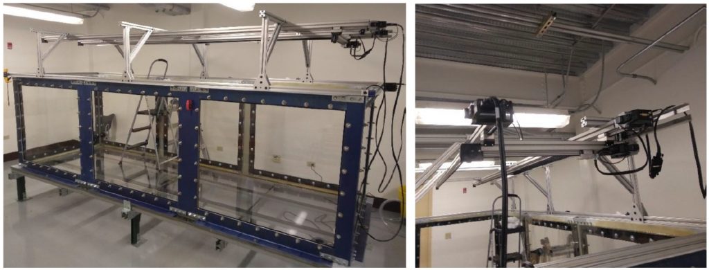
One of the main features of this facility is a large multi‐use fluid testing tank (Figure 1). The tank measures 4.1 m long, 1.3 m wide and 1.1 m high. The tank has a model positioning system that can hold station in a desired static configuration during testing or be used as a carriage for small scale towing tank testing. The dynamic positioning system has two degrees of freedom with 3.5 m of travel along the tank and 1.25 m travel across the width, with a maximum velocity of 0.7 m/s in either direction. The tank is constructed out of acrylic panels attached to a steel frame providing visual access from all sides, facilitating particle image velocimetry measurement of flow fields surrounding vehicles and propulsors. The lab has a full range of data acquisition hardware and multiple workbenches are present for construction, maintenance, and storage of prototype vehicles and subsystems.
Both the Fluid‐Structure Interaction and Nonlinear Dynamics Laboratory and the SUPR Lab are collocated at the UH Marine Center with shared physical space and facilities.
In-Ocean Experiments
The department maintains research facilities at the UH Marine Center in Honolulu Harbor for field work and in‐ocean experiments. These facilities include field research support and instrumentation, a 19‐foot boat, and access to larger research vessels as well as machine shop support.
Instrument and Sensor Development
ORE maintains laboratory facilities with bench and workshop space for instrument development and benchtop testing including access to 3D printers, electronics workspace, tools for minor machining, dedicated wet and chemical bench space, and a variety of support software.
Aloha Cabled Observatory (ACO)
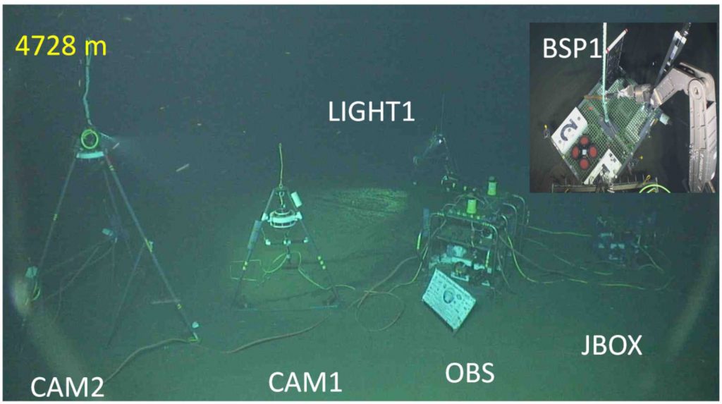
The ALOHA Cabled Observatory (ACO) is a general purpose “node” providing power, communications, and timing connectivity for scientific use at Station ALOHA 100 km north of Oahu. Included are a suite of basic sensors making core measurements as well as local sensing of the water column. At 4728 m deep, it is the deepest scientific outpost on the planet with power and internet connections (Figure 2).
The ACO was deployed in June 2011 to support scientific research. Station ALOHA is the field site of the NSF‐funded Hawaiʻi Ocean Time‐series (HOT) program that has investigated temporal dynamics in biology, physics, and chemistry since 1988, at conditions representative of roughly 70% of the world ocean. Research cruises (~monthly since 1988) sample the ocean from top to bottom to monitor and study changes on scales of months to decades. The co‐located Woods Hole mooring (WHOTS) provides meteorological and upper ocean physical data. Together, HOT, ACO, and WHOTS provide a unique set of complementary in‐situ observations of the ocean across all disciplines and regimes.
The ACO system uses a retired AT&T telecommunications cable. In 2007 the cable was cut and one end moved slightly and a ‘proof module’ hydrophone attached. A general purpose ‘node’ was connected in June 2011 and the ACO has been providing power (1200 W), network communications (100 Mb/s), and timing (1 μs) to the seafloor node and instruments at 4728 m water depth since then. During a service cruise in November 2014, a camera system (CAM2 and LIGHT1) and a basic sensor package (BSP1) were added. Station ALOHA is unique for the combination of long‐term world‐class ocean sampling coupled with multitudes of short to long‐term process studies and other research.
While supporting scientific research, the ACO provides many opportunities for teaching and research within classes, degree projects, and independent studies. These include learning spectral analysis of ambient sound, analyzing the real‐time data, software for displaying raw and video/audio data, developing and preparing instrumentation and infrastructure for deployment, and participating in cruises with leading edge equipment. The SOEST 6000‐m rated remotely operated vehicle ROV Luʻukai supports the latter. ACO is a topic in various classes: ORE 202 Ocean Technology, OCN 363 Earth System Science and Data, ORE 654 Ocean Acoustics, ORE 601 Ocean Engineering Laboratory, ORE 603 Oceanography for Engineers, and ORE 766 Numerical Methods.
To learn more, watch the UH Sea Grant College Program’s “Voice of the Sea” episode about the ACO.
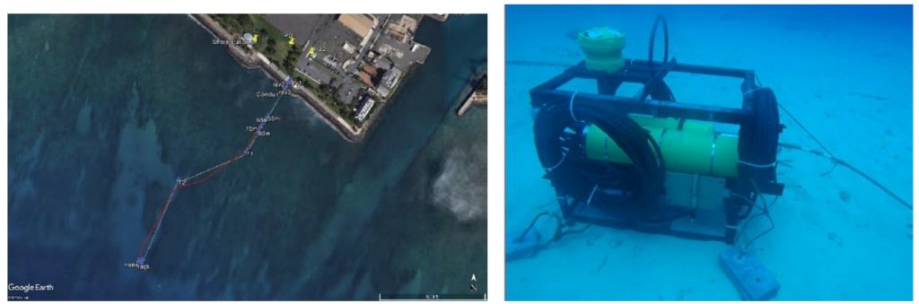
Kilo Nalu Observatory
The Kilo Nalu Observatory (KNO) on the south shore of Oahu provides a window into the nearshore coral reef physical, biological, and chemical environment. The permitted 7‐ acre in‐ocean test range off Kewalo Basin, which extends from 5 to 20 meters depth with test platforms equipped with shore‐cabled power and data connections, provides a direct bridge between lab‐based and in‐situ experiments (See Figure 3). The observatory is managed and maintained by ORE for research on marine alternative energy (a “nursery” site), autonomous undersea vehicle development (mobility and fine control, positioning, docking), artificial reefs, surface waves and currents, new sensors (e.g., pH and alkalinity) and more. A shore‐side radar system provides wide area surface wave coverage. ORE also uses KNO as its “natural” laboratory to train its students, both (future) undergraduate and graduate, for ocean instrumentation, field work, data analysis, and team work.
The system currently has one primary node with three ports in addition to an ADCP. New instrumentation related to the above research topics is in the process of being added. The input to the primary node from shore is 400V and 1 GigE ethernet. Each port has circuit breakers, with programmable pulse width modulation to handle turn‐on current surges, and its own independent ground fault monitoring circuitry (48 V and 400 V). All raw data is logged and plotted in real time. The system hardware, software, data management, and web services are all based on and shared with the ALOHA Cabled Observatory (ACO) and are consistent with de facto international “observatory standards.” ACO uses KNO as a test bed.